
Before we start the reassembly, lets replace those outdated W5W position lights. They would not be a good match for our super-bright HID headlights, so we will replace them with high-performance LED's
The new lamps are available as straightforward replacements from specialized motor factors (see the parts list page). Here is a picture of the old filament sidelights we are about to get rid off:
And here are two samples of the replacement LED sidelights that you can buy these days and which will directly fit into the socket of the outdated original lamp. On the left is a 1.5 Watt single LED sidelight pointing directly forward.
Just for comparison I am showing an extreme-angle sidelight on the right; this type contains 5 LED's with a total power consumption of 3.4 Watts. As you can see from the configuration of those LED's, this type gives an illumination angle in excess of 180 degrees. For our Tiger this type is ideal and it is the one I am using on my Cat.

Note that all LED lights are polarity sensitive, i. e. they will work only if fitted correctly. If you put the LED light into the socket, but the light does not work, then simply take the light out and put it back in the other way round.
The life expectancy of such LED sidelights is 25000 hours of operation or more, so you will probably never have to replace them again during the lifetime of your motorbike. Just remember that these lamps are quite sensitive to water and dust due to their complex electronics, so treat them carefully.
But now let's return to our bike; first we will install the two ballasts on the Tiger. The ballast itself is also getting pretty hot during operation, so we must install it away from plastic components and in a well aired spot. For this the Triumph Tiger provides a brilliant space just inches away from the headlights; the alloy mounting bracket which supports the entire front end of the bike. We begin by attaching cable ties through the three lugs of the metal casing of the ballasts:

Now position one ballast module on each side of the mounting bracket. Position the ballasts so that they touch at the rear end against the bolt heads of the bracket bolts. Ensure the ballasts are flush against the metal of the mounting bracket to ensure perfect heat dissipation. Use cable ties to firmly secure the ballasts in their position.

This is the left side view:

Double-check that you did a proper job and that the ballasts do not interfere in any way with the steering; it must be possible to move the steering all the way without the forks touching the ballasts.
This is the right side, fully positioned and fixed:

Now we can tackle the wiring of the new system. Unfortunately there is no existing circuit available on the Tiger that will support the startup power required to fire up twin HID lamps. It is necessary to create a new wiring circuit for this purpose. The picture below shows the base wiring loom and its components. In this loom both ballast connectors have been soldered into one feed cable which is not what we are going to use as it lacks the time delay unit (I only found out later that a timer is needed, at which stage this cable was already in place on my bike). And if your design incorporates a separate high/low beam lamp, then you must change the layout accordingly.
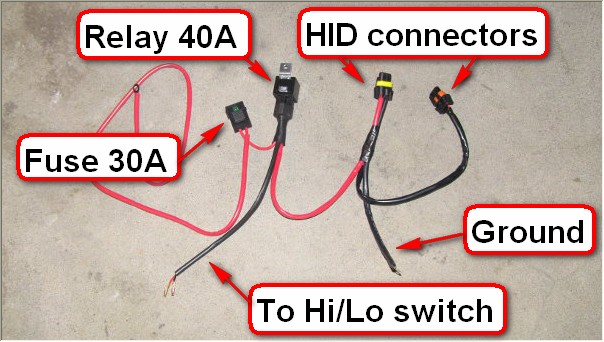
The above cable layout is not entirely correct; the cable that links the 40 A main relay to the 30 A fuse must be much longer, as the fuse will be installed close to the motorcycle battery while the 40A relay will be installed above the headlight assembly. The cable from the 30A fuse to the battery will be only about six inches long (see instructions below). And the black/orange HID connector will need to have the timer unit installed into its power cable to ensure that the second HID fires up 3 seconds after the first one. But still the picture will give you a rough idea what you have to build.
The first step is to shorten the main power supply cable to about 15 cm (six inches). We will attach this cable to the motorbike battery. This means that those 15 cm cable from the battery to the fuse holder itself are unfused. Be very careful when following the next steps; you must ensure that this length of cable can not chafe, is only routed through insulating plastic bike components and does not touch any metal parts.
Of course you should be very careful whenever you work on your bikes electric system, but this step is extra important. As you can see, I have placed an extra insulation tube over the cable - you have been warned...

On the "other" side of the fuse, fit a cable of approx. 130 cm (50 inches). This cable will run all the way from the battery bay to the front headlight, where we will install the 40A control relay. But first we have to install the fuse holder. To do this, remove the bike battery and the alarm/immobiliser unit (if fitted). Pry the rubber clip of the starter solenoid of its plastic lug. Remove the white plastic cover from the solenoid (see picture below) to get access to the battery terminal bolts:

Unbolt the battery terminal and add our power supply cable. Re-fit the bolt (see image below):

The result should look like this:

Route the cable along the power cable that links the solenoid to the starter motor (see image below):

Refit the alarm/immobiliser (where fitted). Tie the fuse holder in position (see image below). Ensure that the unfused cable is routed properly and securely. The fuse should of course be easily accessible like in this image:

Place a 30A fuse into the fuse holder. From the starter motor route the power cable along the main wiring loom on the right side of the bike between the rocker cover and the fuel tank. Ensure that the cable does not chafe anywhere and does not interfere with the steering. Next we do connect the negative earth cable. A suitable position for connecting this cable is the guide bracket on the right side of the frame (see image below). The earth cable is in position, but the bracket bolt is still loose:

The next step is the reassembly of the headlight unit. Start by thoroughly cleaning the individual components. No dust and no remnants of the sawing or the mastic must be allowed to remain. Leave the original wiring and the original connectors inside the headlight unit in place. They will be required should you want to revert from HID to the original headlights at a later time.
The power feed of the new HID lights is achieved through two additional cables. To route these two cables, drill two 8 mm holes, one on each side of the original cable, into the headlight unit:

Clean the rugged edges of the holes and guide the new HID cables into the lamp housing. These cables must be protected from contact with the hot metal of the lamp housings, so as you can see here I have placed mesh over them to ensure that they are protected:

As you can see in above image I have placed black screw terminals at the end of the cables. These terminals will be used to connect to the HID lamps - they are heat resistent and reliable. To seal the holes drilled into the housing I again use epoxy raisin, because it is air- and watertight and perfectly suitable for the job. Use sealant on the inside and the outside to ensure that no dirt or water can penetrate the housing. This image shows the outside of the housing:

Now re-fit the cleaned metal lamp assemblies back into the housing. Ensure that the screw connectors of the new HID cables are properly positioned next to the original connectors at the rear of each lamp assembly:

For the re-fitting of the front "glass" I have tested a variety of seals. The one thing we do not want to use is mastic like the original maker of the headlight unit in Spain uses - we want to retain easy access to the lens units whenever they need cleaning. After many failures I came up with the solution of using watertight textile tape (gaffer tape) to seal the front glass to the main housing:

This looks pretty rough, but it is the only method I could come up with that is entirely water- and dust-proof and that can be easily removed at a later time. Two layers of tape applied in above way ensure a proper seal - and after re-assembly the tape will be absolutely invisible.
Next put the HID lamps into their respective sockets and connect the screw terminals. Note that the original connectors for the H7/H9 lamp are also still in place:

Put the two rear caps back over the opening in the lamp housing using the four screws holding each cap in place. The headlight unit is now ready for re-installation on the bike.
Now it is time to wire up the time delay unit. If you use the same part than I did (see the parts list at the end of this manual) then the unit can be set to different delay times. Any HID lamp will take several seconds from the moment it is switched on to the time when it reaches full illumination. The critical point however is the first second when a very high load is required to ignite the HID lamp. The battery of the Tiger is undersized at the best of times and starting two HID lamps at the same time could lead to one or both of the lamps not igniting. The load for igniting the HID's is particularily high when the lamps are already hot (i. e. being switched off only for a short time and the re-ignited), so to ensure reliable function under all conditions will require to ignite the second HID after a short delay. After various tests I do recommend a three second delay, which can be achieved by setting the relevant dip switches on the timer unit. Here is the unit fully wired up for installation:

I have used a regular power supply plug from an ordinary computer ("Computer plug 4x"). They are ideal for the purpose of connecting electrical items on a bike, because they are made to the same specs as the plugs and connectors used as standard on a motorbike. They are also able to withstand the high load when the HID is igniting. In above computer plug the red and top black cable are used supplying ground and 12V feed to the timer unit. The yellow and bottom black cable are switched by the build-in relay of the timer unit. The timer unit itself is rather bulky and you can get much smaller units doing the same job. The advantage of this specific model however is the build-in relay. This relay is strong enough to withstand the load when igniting the HID lamp, so there is no further need for a dedicated relay to start the second HID. For details of the wiring view the schematic wiring diagram on the parts list page.
If you do not have a computer connector plug ready at hand, then visit your nearest computer shop: they usually have tons of these connectors and you should get a few male/female ones for free or for very little money.
You can get proper boxes to house the timer unit, but such boxes would make the already rather bulky unit even bulkier. It would be very difficult to place a boxed unit into the limited space above the headlight unit. Instead I have opted to seal the unit with watertight tape. My finished unit looks like this:

By now the front end of your bike should probably look as unkempt as mine did before re-assembly:

The power feed into the second ballast must now be routed through the time delay module. The idea is that the moment the main 40A HID relay is activated via the High/Low beam switch on the handlebar, power is routed directly to the first HID ballast. The first HID lamp ignites immediately. The power from the main 40A HID relay at the same time is also powering up the time delay unit. After three seconds the time delay unit will activate its own relay on the platina and this relay will then route power to the second HID ballast, igniting the second HID lamp three seconds after the first lamp.
Note that the capacitors in above image will conveniently disappear inside the alloy mounting bracket on which we fitted the ballast modules.
We are now ready to re-fit the reassembled headlight unit. Note that in the images of the bikes front end a few cables appear which your bike may not have. They belong to the thermometer, the GPS, the gear indicator and the thermostat of the heated gloves (yes, I know, I am a pansy...). The image below shows the position of the HID control relay. I have used a rubber holder to clip it on a free lug conveniently provided by Triumph for that purpose. Your Triumph dealer should have these rubber holders in stock. To the left of the relay you can see the white connector for the (yet not fitted) time delay unit:

Tidy up the wiring using cable ties. Then wedge the time delay unit under the dash panel holder like in this picture and plug in the connector:

Refit the rest of the cowling, the inner panels and the indicators.
For operating the main 40A control relay you could fit a separate switch on the handlebar. I opted to use the high/low beam switch of the bike, because with the system as I fitted it, it has no practical use. This means that on "low beam" switch position only my position lights are on while the HID lamps are off.
Those position lights, now being high-powered LED's are already much brighter than those antiquated glow-worms originally fitted:

One flick of the Hi/Lo switch to the "High"-position now unleashes the light that Triumph should have ordered the Rinder company of Zamudio in Spain (which makes the headlights of the Tiger for Triumph) to provide them with in the first place:

Three seconds after the first lamp the second HID fires up. These headlights with HID lamps are perfectly adjustable and do in no way produce any more glare then HID headlights purpose-built for HID lamps.
Should it be necessary to convert back to the original "glow-worms" at any time for the MOT, TÜV, contrôle technique, WOF or whatever it is called in your part of the world, then this can be quickly done: just remove the rear plastic covers, take out the HID lamps, place the original H7 and H9 lamps back in place and re-connect the original lamp connectors which we wisely left in place when doing the conversion. The same applies to the position lights.
Each HID lamp consumes 32 watts of power. The ballast adds another 10 watts. The position lights consume only just over one watt, so all in all the illumination in above picture consumes 85 watts. The original lamps used 65 watts on low beam and 125 watts on high beam. Given that I now have more than five times the light I had with the original light system then I suggest that the conversion is worth the effort from the point of biker safety alone, especially if you live in a country with compulsory daytime low-beam headlight.
I have prepared a parts and supplier list if you wish to carry out a similar modification